Greg Korner |
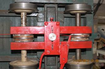
Worm geared brake system |
|||||||
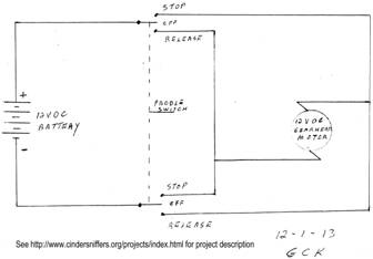
· The 12 volt DC worm gear is controlled by a six pole momentary contact paddle switch with a center off position. · A circuit drawing is in the pics. · When activated the motor rotates an arm which is connected to the brake arms by a 1/16" diameter SS filler wire. Maximum recorded pull was 50 pounds at the most inward attachment to the arm on the gear head. · When it stalls the motor’s maximum current draw is about 8 amps. · When activated to release the brakes, the arm hits a stop and again will draw about 8 amps, if you don't let go of the paddle switch. · I found that by "bumping" the paddle switch in either on/off I could control the amount of braking from just a little to totally locked up. · The arms push the 1/2" x 1" bars (brake beams) together against the steel shoe back plates that have 1/4" thick fiber board material contact cemented to them. · This squeezes the 1/8" thick x 3" diameter brake disk which stops the wheels. · I pressed off one wheel of a truck/axle and slid the brake disk on and anchored it with set screws. · The distinct advantage to the gear head being a worm gear is it stays where you put it; no power needed. When you park it, it won't budge until you release the brakes. · Unlike an air system there is no storage tank, or pumps, or regulators, or leaking air lines to contend with. · All you have is a $20 gear head motor, a $34 gel cell, and a $5 paddle switch, and of course some time building the brakes. · To make the disks I bought 3/16" thick x 4" diameter washers at the local tractor store and faced them on both sides after silver soldering them to a 1-1/2" hub bored 1-1/2 thousandths over .750 which is what all my axles are.
I had long ago decided that there had to be a better way to brake a train than the conventional shoes and air brake design. Now I have a system that I would be glad to share with anyone who wants to build it. If anyone has questions, contact me via email.
Respectfully submitted, Gregory Korner [lookoutmntrr@wildblue.net] 12/20/2013
|
Go to "Brake System" for additional photos.
|
|||||||
|
||||||||
Carl Schwab |
||||||||
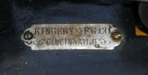
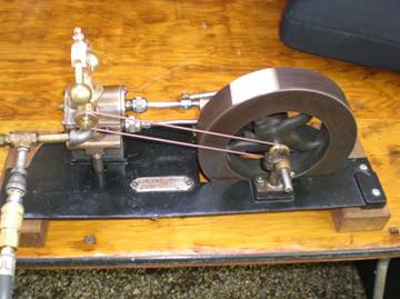
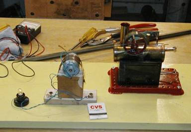
The engine shown here is a Kingery popcorn engine, made by the Kingery Manufacturing Co., Cincinnati, OH, in the late 1800’s. Although Kingery listed Cincinnati as its home, it is believed the engine was actually built in Hamilton, OH. Cretors is the name that usually comes to mind when thinking about popcorn engines, but Kingery actually preceded this Chicago company. I think this size engine is unique because it has a piston valve. This valve being of poor fit prevented the engine from operating until a new valve was made. The other chore was building a governor for the engine. The governor shown is a Cretors governor that I built and fitted to the engine. It was quite a challenge to build. It is always rewarding to overcome a challenge and see the results. The author does not own this engine.
Oct 2009 |
|
|||||||
|
||||||||
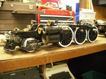
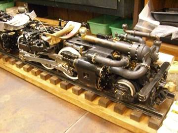
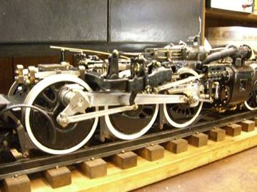
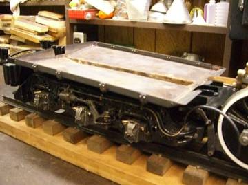
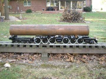
Chuck Balmer’s 3/4 scale 2-6-6-6 Allegheny Locomotive
View Chuck’s progress on our PicasaWeb pages in the projects folder: http://picasaweb.google.com/CinderSniffers/Projects#
Jim posted videos of our Hudson running at the track Oct. 11,2010. The video takes you around the entire track both upper and lower loops. Here is the address:
Oct. 11, 2010 http://www.youtube.com/watch?v=_9b9AoCgy6g
Oct. 8, 2011 http://www.youtube.com/embed/WQz-cxJFWgw
In June 2010 he added two views of the smokebox and a breakdown of the boiler feedwater pump.
|
||||||||
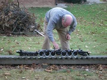
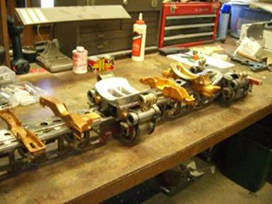
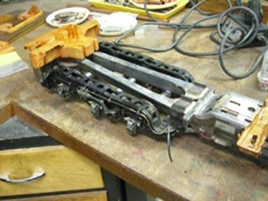
November 2008: The first pictures are of the front and rear engines before being coupled together. The next 2 photos are of the clearance and tracking tests of the coupled engines on our backyard test loop. While some adjustments to the suspension will need to be made, the tests went well. The next phase of the project after the brake rigging is complete will be to make the connecting rods. If all goes well, I hope to have the chassis ready for air tests next summer.
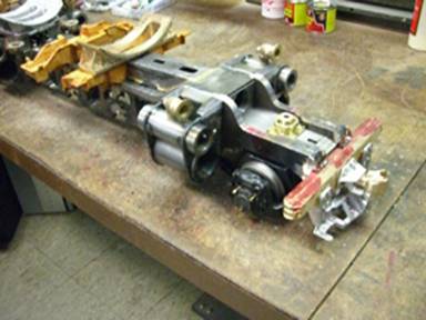
May 2008: The photos show a front and side view of the entire chassis, a side view of the rear 6 wheel truck and a side view of the front 2 wheel pilot truck. The valve gear supports are actually the wooden patterns that have yet to be cast. I hope to have them finished sometime this summer. The frames are fully welded and I am getting ready to fininsh silver soldering the steam passages in the fabricated cylinders. Once the remaining castings are finished, they will be machined and work will begin making the 4 baker valve gear assemblies and the 4 sets of connecting rods. The 12 drive wheels have been cast and machining them will begin soon.
Since I am still a couple of years away from finishing, I will send updated photos as the work progresses.
|
||||||||
|
|
|
||||||
|
|
|
||||||
|
|
|
||||||
|
||||||||
|
||||||||
Steve Harrod |
||||||||
This is a fun project I made with a motor salvaged from an inkjet
printer. |

|
|||||||
|
||||||||
|
||||||||
Denis Larrick |
||||||||
|
||||||||
|
||||||||

 The
driver motors (not the stepper motors) on these printers are very
high
The
driver motors (not the stepper motors) on these printers are very
high
 2.5"
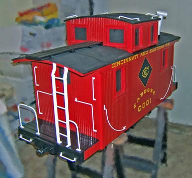
scale narrow gauge caboose based upon the eight wheel, 17 foot
Class 4 caboose on the D&RG and Rio Grande Southern. It is a
plywood toolbox with removable roof, sheathed in strips of
salvaged paneling from my living room. The side shown
to the right is painted to resemble 1880 practice, the other side
is painted in early 1900’s style.
2.5"
scale narrow gauge caboose based upon the eight wheel, 17 foot
Class 4 caboose on the D&RG and Rio Grande Southern. It is a
plywood toolbox with removable roof, sheathed in strips of
salvaged paneling from my living room. The side shown
to the right is painted to resemble 1880 practice, the other side
is painted in early 1900’s style.